Getting Started
This is a brief introduction to Caneda’s functionalities to get you ready on track. There are basically two ways to get started using Caneda right from scratch:
- Using the schematic context and creating a new design
- Using one of the circuit examples available from the Example Circuits repository.
Interface Introduction
In the following image the Caneda main window is shown, along with the initial tools and default configuration. The user interface is fully configurable, and you can show, hide or move any tool to your personal preferences.
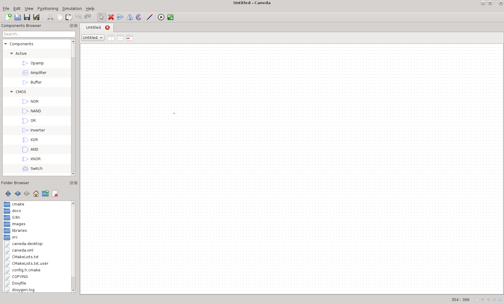
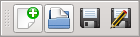
The file and edit toolbars contain general tools, available in most programs today. They don’t need any introduction, as their tools are common knowledge.

In general, there can be several contexts. In Caneda terminology, a context is a type of document you can edit for a certain task. For example, a schematic capture is one of Caneda’s contexts. Other examples include a symbol editing, a simulation view, a layout editing. Every context has a set of tools and components associated with it, which you can use only in that context. For example, inserting a wire is useful if you are editing a schematic, however if you are analyzing a simulation, inserting a wire has no sense. In that case, inserting a cursor may be more applicable to that particular context. The following tools are all context sensitive, changing depending on the current context you are working on.
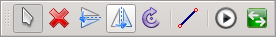
The main toolbar shows the more frequent options, giving you easy access to the needed tools for the current context.
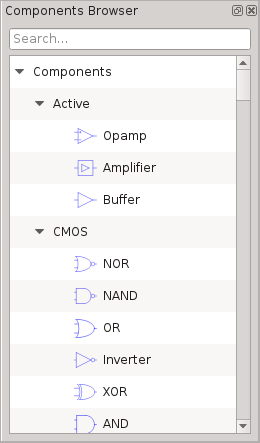
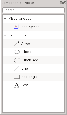
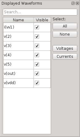
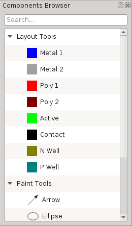
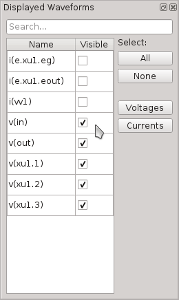
The sidebar browser is one of Caneda’s most useful tools. In the following images you can see it in action for the schematic, symbol, layout and simulation contexts. To use it, simply select a component from the tool and start inserting it right away in the current view. In the case of the simulation context, you can select or deselect the waveforms of the view. The sidebar browser has a convenient filter tool, to display only those items you are interested in. As a shortcut to the component filter you can press the c key on your keyboard.
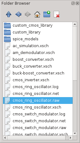
Finally, the folder browser allows you to easily access your files from a convenient place and open them right from the Caneda interface.
Create a New Design
In the following example, we will introduce the basic usage by creating a simple opamp based amplifier. To start a new design, click on the New icon from the file toolbar.

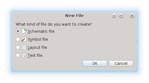
A New File dialog will open, giving you the option to choose between several file types. For this example, we will create a new schematic file. Select the Schematic file option and click OK.
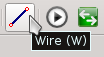
Alternatively, if you just started the program, you could have used the already opened new schematic document. Start editing you schematic, by adding components from the sidebar browser and wires from the main toolbar. The following image shows the wire tool. When you are in doubt what action performs each tool, just leave the mouse on the selected tool for a couple of seconds, and a tooltip will appear.
Using the previous tools, create an schematic as the shown in the following image.
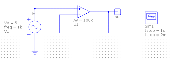
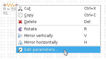
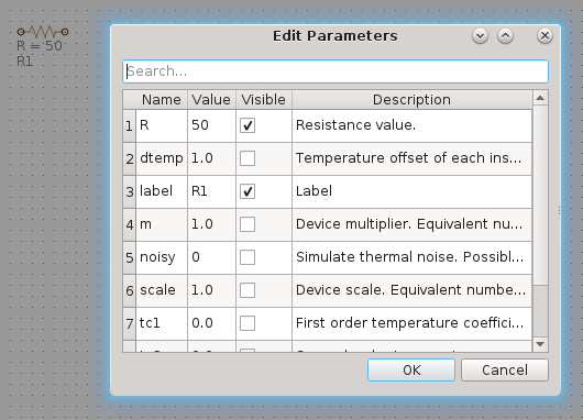
To edit a component property, for example the impedance value in a resistor, double click on the inserted component or select the Edit parameters... option on the context menu (by left mouse clicking on the component).
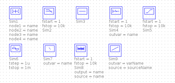
To perform any simulation it is always important to add, besides your desired components, at least one ground component and a simulation profile.
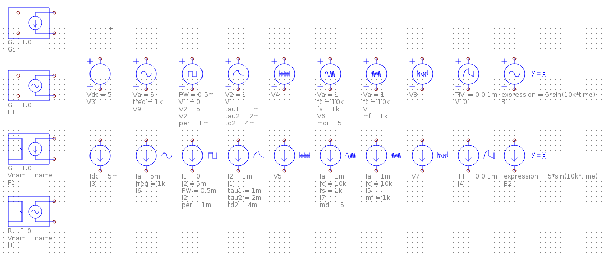
To get a meaningful result, you should also add a source.
Once you are done, you are ready to perform your first simulation in Caneda.
Performing Simulations
To start a new simulation, click on the simulate tool in the main toolbar.

Once the simulation is finished, a new document will open with the simulation results.
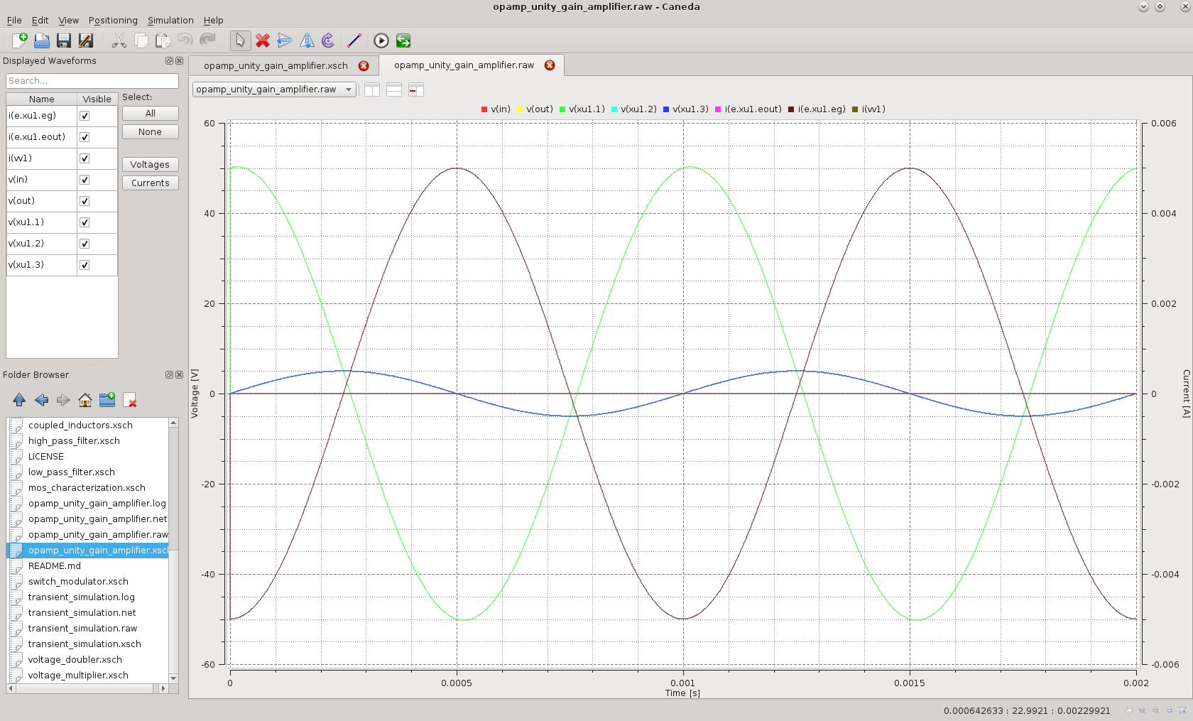
To select the displayed waveforms, click on the Visible option from the simulation sidebar.
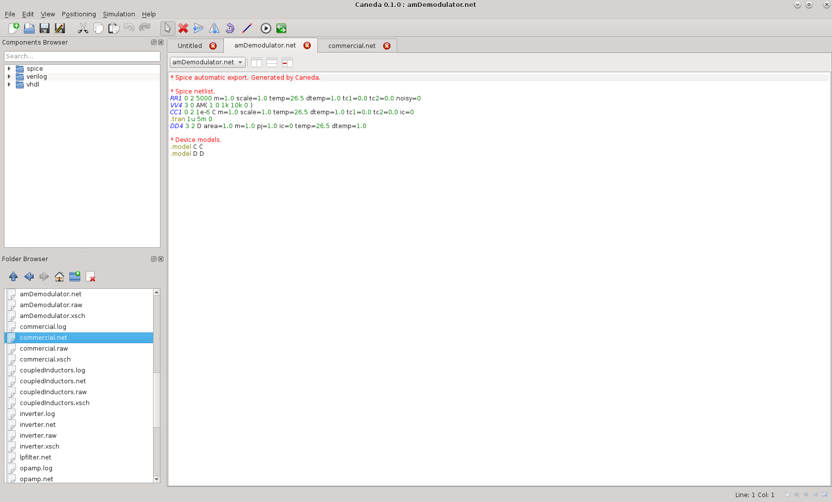
Text editor
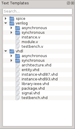
Caneda has an embedded text editor, which allows you to create and design all kinds of text code based simulations. The most common forms are spice and hdl (verilog and vhdl) simulations. To help you realize your design, a ready to use set of templates is available from the text sidebar. Once you have your design ready, just click on the simulate tool as in the above example and Caneda will perform the simulation for you, using the appropiate tools.
Circuit Examples
There is a repository hosted at Example Circuits which contains example circuits for Caneda, ready to use. The example circuits are continuously updated and improved, and periodically new circuits are added.
To try any circuit, simply download the selected schematic to your machine and open it using Caneda. All circuits are ready for simulation using Caneda’s tools. Inside each schematic there are specific details to the circuit, where applicable.
As an alternative you can download the whole repository and save it in any local folder to have as a reference.